


01
Prepare water
Review source-water conditions and the treatment required by the selected equipment.
Follow the water, the feed and the controls—from electrolysis to the point of use.
Conditions depend on the equipment route.
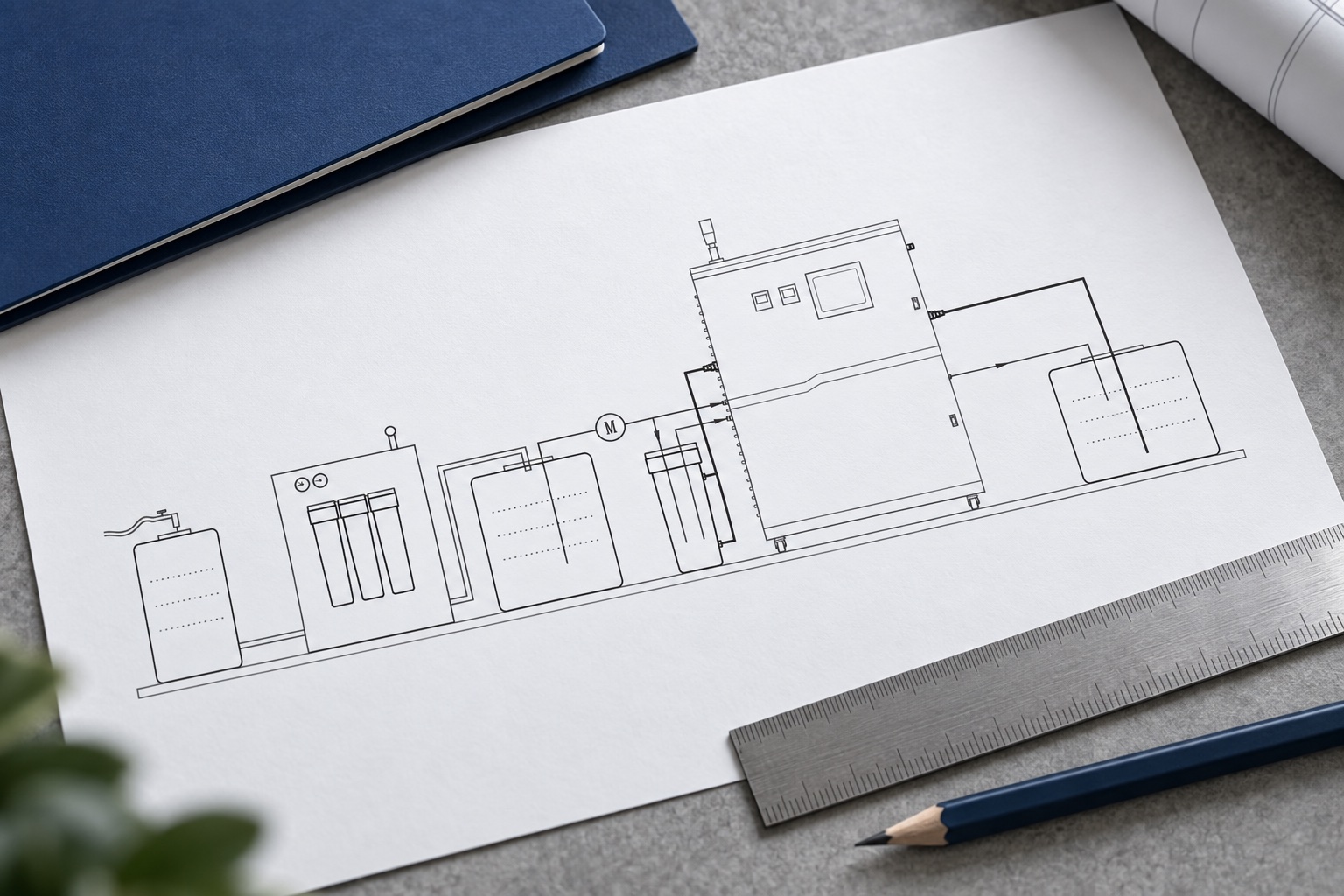
Follow separate water and feed paths through electrolysis, sampling and two delivery arrangements. This functional animation explains the process; equipment arrangements vary by model.
Select a stage for the buying question behind it. All stages remain visible below.
Review source-water conditions and the treatment required by the selected equipment.
Use the feed material and preparation method specified for the electrolytic cell and generator.
Metered water and feed enter the electrolyzer. The electrical supply drives electrode reactions; flow and operating settings affect the generated solution.
Sample or monitor the generated solution using the agreed measurements and method. A setpoint is a target, not proof of the measured result.
Some projects use direct supply; others need a buffer tank and delivery equipment. The arrangement depends on demand and site conditions.
Storage, distribution and process conditions can change the solution before use. Check the conditions relevant to the intended application.
Xiaoya offers HCl-fed and salt-fed equipment. Feed preparation and water requirements must match the proposed model.
Review the specified acid feed, metering arrangement and water conditions for the AQ-P configuration. Feed preparation is an operating requirement to confirm with Xiaoya.
Explore the AQ-P familyReview salt-feed preparation, the specified water-treatment arrangement and any auxiliary tanks or pumps. Confirm the quoted package for the selected salt-fed configuration.
Explore salt-fed equipmentElectrolysis happens in the electrolytic cell. Reliable operation also depends on the water, feed, electrical supply and controls around it.

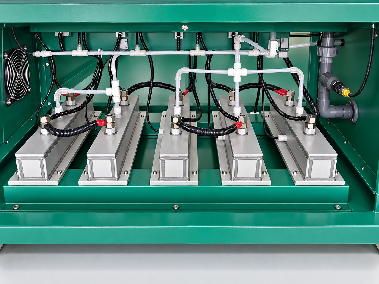
The electrochemical reactor. electrolytic cell design, condition and feed requirements belong to a specific equipment configuration.
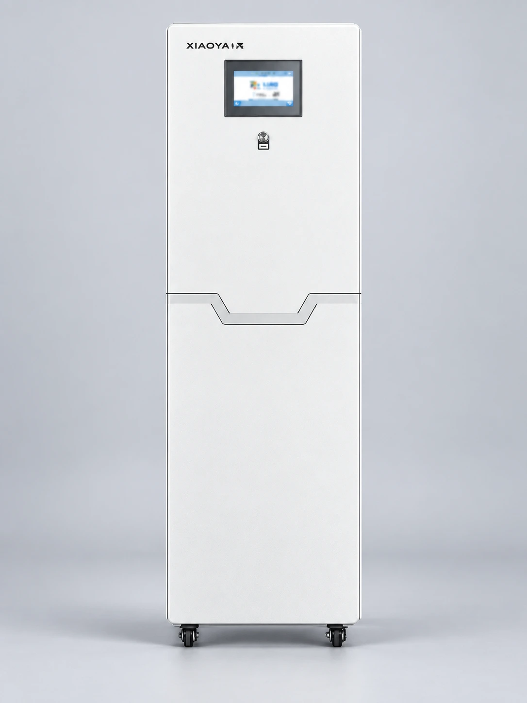
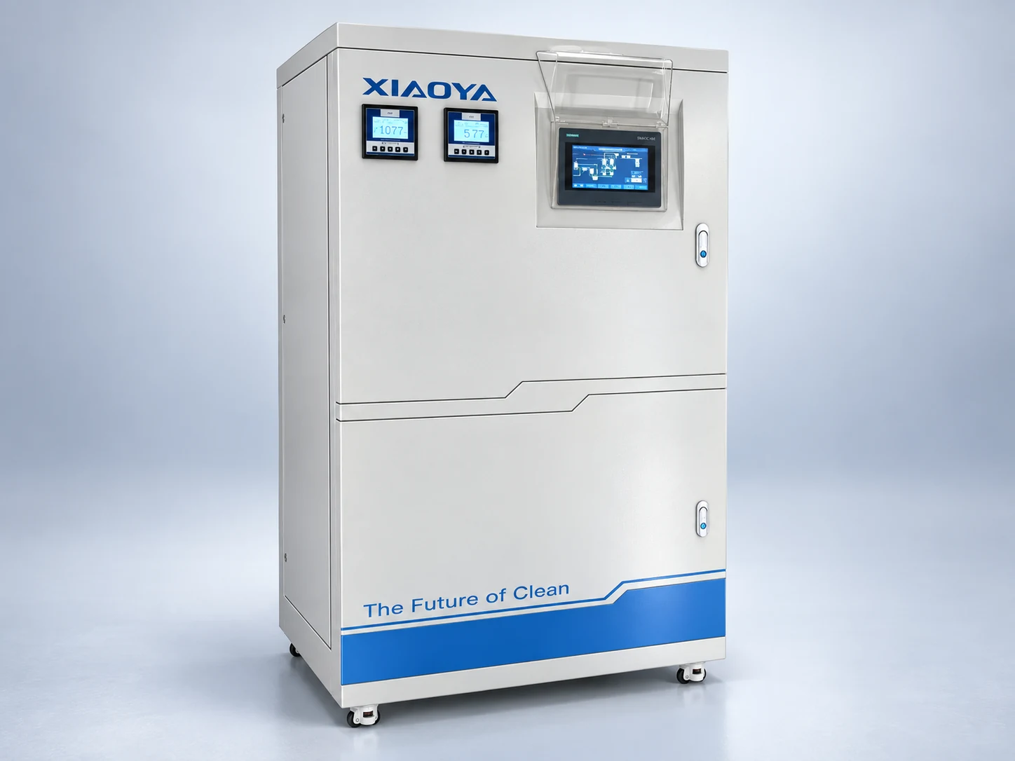
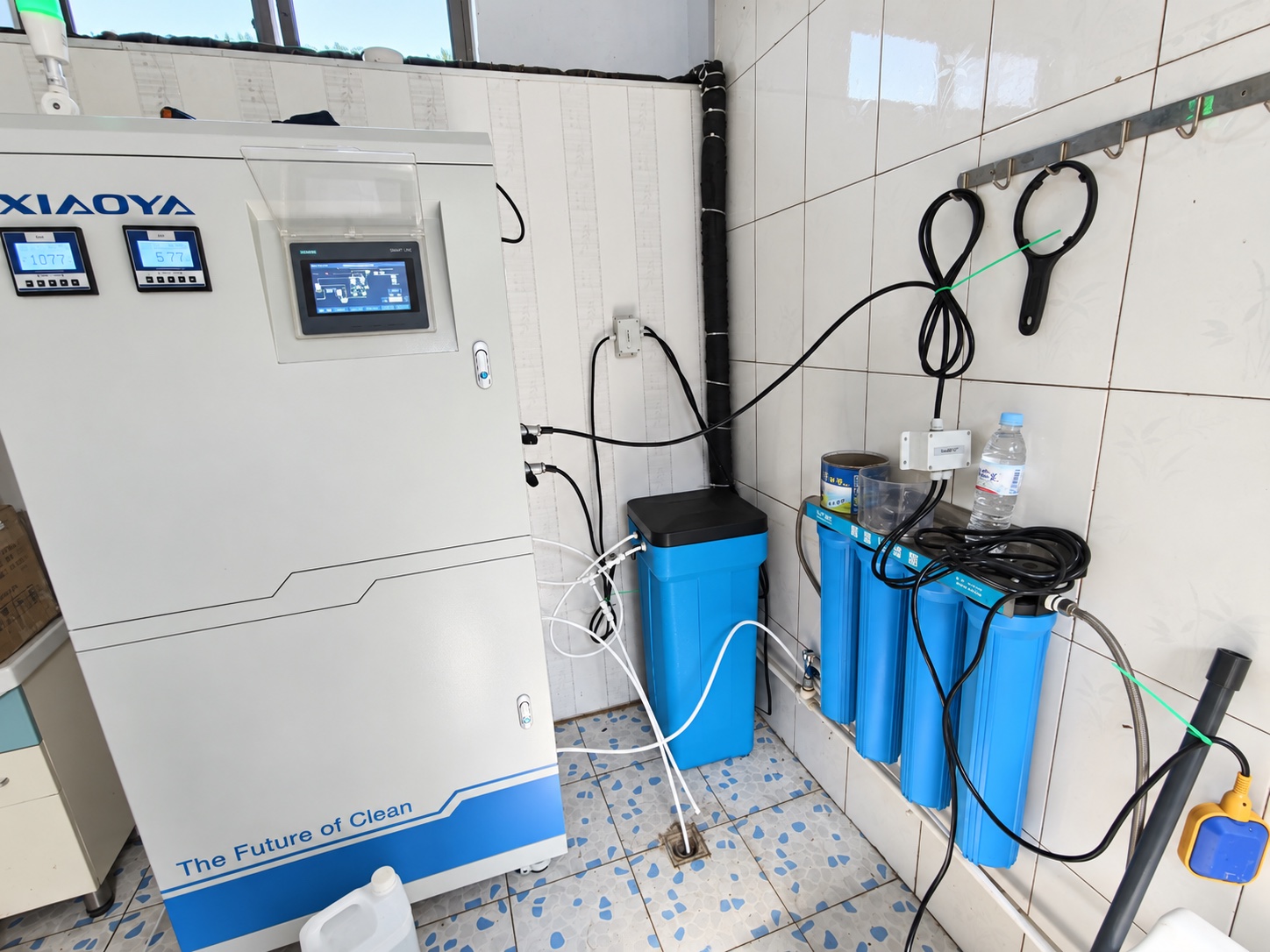
The electrolytic cell with its water/feed handling, power and controls. Confirm what is built into the selected machine.
May add water preparation, storage, delivery and connected controls. Identify included, optional and customer-supplied equipment.
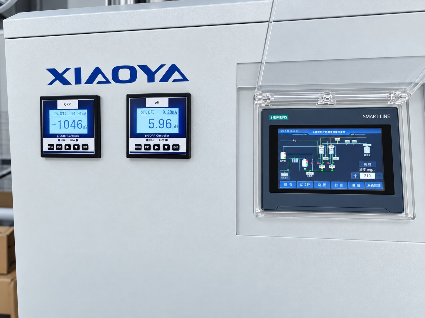
See system scopeThe commanded target in the controller.
The generated stream, checked at defined operating conditions and a defined sampling point.
The solution after any storage, distribution or dosing. Its suitability depends on the application.
FAC describes free available chlorine. pH describes acidity/alkalinity. Specify what is measured, where and by which method; do not treat a displayed value as proof of application performance.
Review these conditions alongside the quoted output. A capacity figure is meaningful only with its operating conditions.
Water quality and feed preparation affect chemistry, scaling and operating consistency.
Generation conditions work together. Do not assume the maximum flow and maximum concentration occur simultaneously.
Deposits and component condition can affect operation. Follow the maintenance guidance for the selected model.
Time, storage conditions and delivery arrangements can change the solution before it reaches the process.
Agree the checks for your equipment and project before delivery. The scope and acceptance criteria belong in the quotation and purchase documents.
Use the quotation comparison worksheetWater, feed, utilities, equipment layout and the supply responsibilities.
Output flow, FAC/pH, operating conditions, sampling methods and required records.
Applicable alarms, interlocks, restart behavior and operator actions for the proposed configuration.
Outlet and use-point checks, installation responsibilities and handover documents.
Storage requirements depend on your operating conditions. Some customers supply spraying equipment directly, while others use a buffer tank to manage peak demand.
Also define the generated concentration, daily and peak demand, operating hours and site conditions. Compare output figures under the same stated conditions.
No. Confirm which measurements and alarms are included, how they are checked and what operators should do when a condition is outside the agreed range.
Share your use point, expected demand and available water information. Unknowns can be discussed with Xiaoya.